Fig. 5.46. Correspondence between AleC++ and VHDL-AMS
VHDL-AMS modeling environment in Alecsis is also supported by the compiler described in the previous section.. The co-simulation concept is the same as it is shown in Fig. 5.42.
Since AleC++ resembles the semantics of standard HDLs, such as VHDL-AMS, the correspondence between language elements can be easily established (Fig. 5.46).

Fig. 5.46. Correspondence between AleC++ and VHDL-AMS
For describing of continuous systems VHDL-AMS uses the theory of differential and algebraic equations (DAE’s). A new class of objects, the quantity, is introduced to represent the unknowns in the system of DAE’s. Also, special kind of quantities called branch quantities are used for representing the unknowns in the equations describing conservative systems (systems obeying Kirchhoff’s laws). There are two types of branch quantities: across quantities (for effort like effects such as voltage or pressure) and through quantities (for flow like effects such as current or fluid flow rate). They are declared with reference to two terminals representing nodes of the module. AleC++ uses a similar language element called link to describe quantities that appears on a module terminal and represent the unknowns in the behavioral system descriptions. There are five types of links in AleC++: node, current, flow, charge, and signal. Obviously, node corresponds to a terminal and current to a through quantity. The flows represent general analog quantities and correspond to free quantities in VHDL-AMS. Simple simultaneous statements used for notating DAE’s in VHDL-AMS relate to appropriate AleC++ constructs for writing equations. Since the way of writing equations is almost the same in both languages VHDL-AMS compiler can easily determine contributions of the equations from VHDL-AMS model to the matrix of the system of equations describing the whole design. It is necessary in Alecsis to explicitly specify to which matrix row the equation contributes. In equations using free quantities that information can be provided as the equation’s label. In equations containing branch quantities terminals can be used to determine matrix rows to which equations contribute.
VHDL-AMS provides conditional and selected forms of the simultaneous statement that allow changing set of equations in the model. Since AleC++ has similar constructs, VHDL-AMS compiler can easily translate those statements into the corresponding object code.
Both languages support signal attributes for derivative and integration over time used in differential equations. AleC++ also supports second-order time derivative attribute and it is implemented in VHDL-AMS compiler, too.
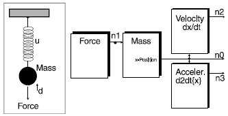
In order to illustrate AleC++/VHDL-AMS mixed-language description and simulation we shall model a mechanical system describing oscillating mass. The structure of the model is shown in Fig. 5.47.

Fig. 5.47. The structure of oscillating mass model
The architecture of the mass is described in VHDL-AMS and defines mechanical equilibrium as a single second-order differential equation using a simple simultaneous statement:
entity mass_e is
generic (m,u,d: real);
port (quantity x: out real;
quantity force: in real
);end entity mass_e;
architecture mass of mass_e is
begin
x: m*x'dot'dot + d*x'dot + u*x - 1*force == 0;
end architecture mass;
Entities for calculating velocity and acceleration are not necessary for simulation, but are used just to print out the appropriate results:
entity velocity_e is
port (quantity x: real;
quantity v: real
);
end entity velocity_e;
architecture velocity of velocity_e is
begin
v: 1*v - 1*x'dot == 0;
end architecture velocity;
entity acceleration_e is
port (quantity x: real;
quantity a: real
);
end entity acceleration_e;
architecture acceleration of acceleration_e is
begin
a: 1*a - 1*x'dot'dot == 0;
end architecture acceleration;
The model stimulus is described in AleC++:
module Force (flow force) {
action (double force_value) {
double force_out;
process per_moment {
force_out = force_value*exp(-now);
eqn force: {force} = force_out;
}
}
}
In order to simulate the system all models are instantiated and appropriate simulation control parameters are defined in a root module described in AleC++:
#include <alec.h>
#define Period 15. s
module mass_mod(flow x, force) action(double m, double u, double d);
module velocity_mod(flow x, v);
module acceleration_mod(flow x, a);
library "mass";
library "velocity";
library "acceleration";
module Force (flow force) {
action (double force_value) {
d ouble force_out;
process per_moment {
force_out = force_value*exp(-now);
eqn force: {force} = force_out;
}
}
}root eq() {
flow n0, position, velocity, acceleration;
mass_mod p;
Force F;
velocity_mod V;
acceleration_mod A;
p(position,n0) {m=1; u=1; d=0.35;}
F(n0) {force_value=10;}
V(position,velocity);
A(position,acceleration);
timing {tstop = Period; a_step = Period/1000;}
plot {flow position;flow velocity;flow acceleration;}
}
VHDL-AMS models have to be compiled first into the AleC++ object code by using VHDL-AMS compiler. Then, the whole system is simulated using Alecsis.
The mixed-language simulation results are shown in Fig. 5.48. Traced signals are positon, velocity and acceleration, respectively.
Fig. 5.48. Simulation results of the oscillating mass shown in Fig. 5.47.